
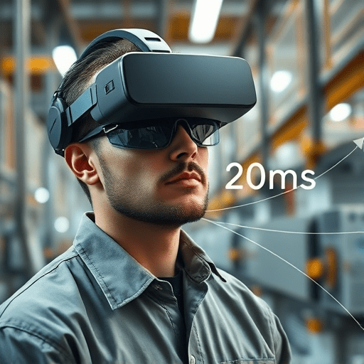
Cut 5G edge latency for AR remote support in 6 steps is the clearest way to turn a promising pilot into a dependable daily tool. The target is not just faster throughput but consistent sub-20ms round trips for spatial annotation, video, and hand gestures. A glance at the network exposes the problem: standard IP routing, default 5G quality-of-service stands, and client-driven bitrate adaptation add delay at every handoff. The answer is an edge-native design that uses MEC location APIs and adaptive bitrate to make the 5G edge do the heavy lifting.
Remote support is a special case. The technician’s device — typically a headset or a ruggedized smartphone — sends a live visual feed to an expert who draws instructions on a remote screen. Those instructions must merge with the physical environment on the technician’s side. The useful latency budget breaks down to about 5 ms for radio uplink, 5 ms for edge compute, 5 ms for downlink, and 2-3 ms for the headset’s rendering and camera sync. Exceeding that threshold produces drift between a real-world object and the annotation attached to it. The six implementation steps below stay inside that envelope, even on a busy site cell.
Step 1: Use MEC Location APIs to Anchor the Session
Most AR services still discover an edge node through DNS-based routing. DNS tends to use the device’s IP address, which, for a moving smartphone, may point to an aggregation location far from the actual radio sector. The result is a usable session that bypasses the closest compute node. That is where the MEC location API changes the game: it exposes the cell ID, tracking area, and even precise indoor positioning zones in a 5G standalone network.
An AR remote-support application can make a single REST call to the MEC host and receive the list of nearby edge servers that are radio-near the technician. The application then anchors both the video stream and the spatial tracking session to that specific node. If the technician moves to another floor or across a site, the location API triggers an application instance migration or a session transfer. This is not traffic steering; it is session anchoring, and it separates a sub-20ms remote-support session from a best-effort cloud tunnel.
Step 2: Put Adaptive Bitrate on the Low-Latency Data Path
Adaptive bitrate has been used for years to deliver video over unpredictable broadband. But standard client-side ABR reacts to buffer changes that emerge seconds after the network becomes congested. For remote support, a 2-second buffer is an eternity. Instead of relying on the player’s buffer, the edge uses the MEC Radio Network Information API — exposed by the 5G RAN controller — to observe radio conditions as they change: reference signal quality, signal-to-interference-plus-noise ratio, packet delay, and available bandwidth.
An edge-resident encoder uses those live radio metrics to adjust bitrate in the same time frame as a network handover. When the technician walks past a metal rack and the uplink quality dips, the edge lowers the camera stream’s bitrate and preserves the small, high-priority annotation packets. When the radio clears, the bitrate climbs back up. The result is a video feed that adapts to the radio without waiting for the user to complain, which is the difference between a 40ms stall and a consistent 18ms experience.
Step 3: Offload SLAM and Positional Tracking to the Edge
Simultaneous Localization and Mapping is the invisible base of AR annotations. The device must know where the camera is in 3D space relative to the object being repaired. Running SLAM on the device provides low latency but consumes power and thermal budget. Running it in a remote cloud adds too much distance. The edge provides the best balance when combined with a 5G uplink.
On a MEC node with a GPU or a neural processing unit, the headset sends a compact set of camera features and receives a 6-DOF pose update 60 or 120 times per second. This offload path keeps the processing loop close enough to preserve sub-20ms while freeing the headset’s main processor for video render and interaction. An additional benefit is a shared map: when two technicians face the same asset, the edge creates a single map that both can use, which makes the expert’s annotations coherent across different viewpoints.
Step 4: Pre-Bind QoS Flows Through the 5G Core
A default 5G PDU session is provisioned for best-effort traffic. Remote-support vendors that wait for the session to start and then request low-latency treatment are several packet exchanges too late. The first seconds of an AR session are the most important, and that is exactly when a session setup delay is most visible.
Through the 5G Network Exposure Function, an edge application can request a dedicated QoS flow before the device initiates remote support. The MEC platform acts as an Application Function and asks the Policy Control Function for a dedicated 5QI bearer with low-latency and high-reliability characteristics. This process is called flow pre-binding. It ensures that the AR video, pose stream, and annotation events travel over a dedicated radio bearer from the first frame. Session setup time drops from more than a second to less than 50 ms, which for a live visual support session is a significant step toward the sub-20ms target.
Step 5: Break Out Non-AR Traffic Early
An AR headset is also a telemetry collection device. It sends logs, battery metrics, usage analytics, and configuration snapshots. When all that data shares the same network slice, the queue delays the AR traffic and pushes latency over the threshold. The MEC local breakout feature allows to split the traffic at the edge, so only the time-critical flows travel the low-latency path.
In practice, this means defining three simple packet categories:
- AR performance traffic: video frames, annotations, pose updates, and control messages on the dedicated QoS flow.
- Device telemetry: logs, non-critical analytics, software update checks sent to a local MEC endpoint or held for the end of the session.
- Background traffic: operating-system updates and cloud backups that can wait for the support session to finish.
Once classified, the edge applies packet marking and local routing rules. The low-latency flow sees almost none of the background noise, and the sub-20ms budget remains intact even when the headset is busy sending diagnostic data.
Step 6: Close the Loop with Edge-to-Device Telemetry
Sub-20ms cannot be taken for granted throughout a full workday. Concrete walls, moving equipment, and changing radio conditions all produce interference. A closed-loop edge controller monitors the live path and makes micro-adjustments before the user notices. The MEC host periodically sends one-way ping probes to the device’s embedded agent, while the core reports radio KPIs and the application reports its own processing latencies.
When a 90th-percentile delay crosses 18 ms, the edge control loop reacts automatically:
- reduces the adaptive bitrate of the main camera stream to free capacity for annotation packets;
- switches the SLAM state to a lighter model to shorten compute time;
- or shifts the session to another MEC instance on the same site.
These adjustments happen in seconds, but more importantly, the telemetry data exposes which of the six steps is the current bottleneck. Over multiple sessions, the collected information feeds capacity planning for the edge node and the radio network layer, which is why 5G edge latency no longer remains a target; it becomes a continuously validated metric.
Conclusion
The challenge of AR remote support is rarely the AR application itself. Routing, session establishment, and buffer greed are what push round-trips past 20 ms. The six steps above align the 5G data plane with the MEC location API and adaptive bitrate, so the edge can perform its part of the AR loop. Pre-binding QoS flows, offloading positional tracking, and keeping telemetry off the critical path are the decisive moves. Once those mechanisms are in place, a sub-20ms AR remote-support session becomes the expected experience, not a lab result.