
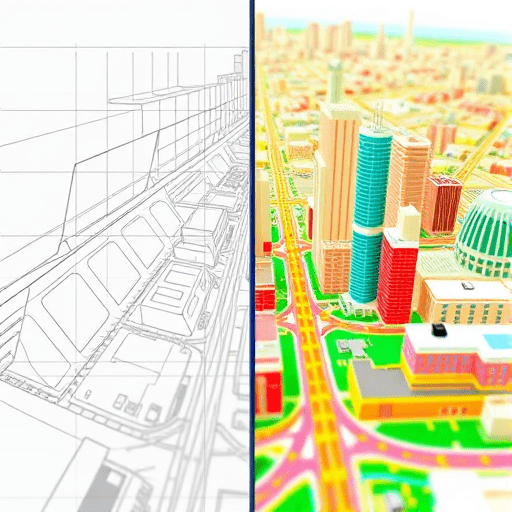
The gap between “just a 3D model” and a truly operational digital twin is narrowing rapidly. For years, urban planners and city architects have stared at their beautifully detailed AutoCAD files, wondering why they can’t simply plug them into a modern, interactive digital twin platform. The old answer was always, “You need a development team.” But in the current landscape, that’s no longer true. The modern workflow to turn city CAD files into a working digital twin has shifted from pure software engineering to data strategy. The process now favors those who understand city structure, not just syntax. This guide provides a step-by-step conversion path designed specifically for non-developers in 2026, focusing on smart preparation, no-code tooling, and semantic clarity.
If you are a planner, an urban designer, or a GIS officer holding messy, layered CAD data and a mandate to deliver a digital twin, this article is your operational manual. We won’t be writing a single line of code. Instead, we will leverage the power of modern spatial platforms, data cleaning principles, and semantic modeling to breathe life into your static floor plans and site sections.
Step 1: Audit Your CAD Data – It’s a Map, Not a Model
The first mistake most teams make is treating CAD files like GIS-ready 3D models. A DWG or DXF file is fundamentally a collection of geometric primitives—lines, polylines, arcs, and blocks—organized by layers with arbitrary on/off states. Before approaching any CAD to digital twin workflow, you must inventory what you actually have.
- Coordinate System: Does your data exist in real-world coordinates (like State Plane or UTM), or is it a local, arbitrary grid? Digital twins require actual georeferencing to align with aerial imagery, other city data, and sensor feeds.
- Layer Structure: Are layers consistently named? Standardized naming (e.g., “A-WALL”, “A-DOOR”, “L-ROAD”) makes conversion much easier than layers labeled “Layer 1” or “CAD_Export_v3_Final”.
- Closure and Geometry: Are your walls drawn as closed polylines or just lines that visually overlap? If the geometry isn’t cleanly closed, volume extrusion will fail in the twin platform.
Performing this initial audit does not require engineering skills—just a curious eye and the Layer Properties Manager. The goal is to identify the “root” layers that matter for the twin, filtering out annotation, dimensions, hatching, and title block clutter that will corrupt your conversion.
Step 2: Clean and Standardize – The 80% of the Work
The secret to a successful digital twin is recognizing that garbage in equals garbage out. In the years of digital twin consulting, industry experts agree that over 80% of a non-developer’s project time should be spent on data preparation and cleaning. This is your major value-add. Modern conversion workflows allow you to focus on this without touching code.
Purge and Explode
Run a thorough PURGE command to eliminate unused blocks, layers, and linetypes. Next, systematically EXPLODE dynamic blocks and nested references. While dynamic blocks are great for drafting efficiency, they retain massive amounts of metadata useless to a digital twin engine. Flattening them into basic solids or polymesh objects ensures the geometry interpreter can read them accurately.
Normalize Z-Values and Levels
City-scale CAD files are notorious for having elements incorrectly placed in 3D space. A wall might have a Z-value of 0, while its adjacent wall sits at Z=10. Use the properties panel to select all base elements and snap their Z-base to zero. Then, utilize a custom layer-state or level mapping table (in Excel) to assign heights to different building components. For instance, Layer “A-WALL” gets height 3.2 meters, and Layer “A-CURT-WALL” gets 3.5 meters. This semantic height assignment is the bridge to 3D generation.
For non-developers, this is where GIS tools like QGIS (open-source) or FME (no-code visual data transformation) excel. These platforms allow you to set up “if this layer, then this height” matrices visually. You will spend your efforts here, but this is also where the “magic” of a good twin is won.
Step 3: Choose a Twin-Ready Platform with CAD Magic
In 2026, we have moved past the era of needing to code Unity or Unreal Engine to get a digital twin. Several robust platforms accept CAD files directly, or via simple geodatabase connectors. When selecting city planning software, look for these native CAD import features:
- Esri’s ArcGIS GeoBim: Seamlessly integrates Revit and CAD via the ArcGIS Pro interface, maintaining georeferencing automatically. Ideal for urban planning projects already using the ArcGIS ecosystem.
- Autodesk Tandem: The perfect low-code platform for those already in the Autodesk ecosystem. It treats CAD and Revit as first-class citizens, allowing you to upload and immediately visualize data.
- Open-Source Stacks (QGIS + Cesium): For teams with tight budgets, QGIS can convert CAD layers into shapefiles and 3D Tiles. The Cesium ion plugin allows you to stream these 3D city models to the web without writing a single script.
The primary task here is mapping. You are mapping the CAD layer names to your platform’s data schema. Choose the tool that aligns with your budget and existing IT infrastructure, not the one with the most “bells and whistles.”
Step 4: Semantic Mapping – Give Your Walls Meaning
Geometry alone is just a sculpture; semantics make it a digital twin. Step 4 is where we transform a rendering into a data-rich database. In this step, you will add attributes to every 3D object: building name, construction year, function (residential, commercial), and fire safety zone.
How does a non-developer do this efficiently? Through the power of attribute field mapping. Most modern platforms provide a “Join” or “Map Attributes” function. You connect a text-based CSV file (exported from your asset management system) to the visual geometries in the twin.
A pro tip for 2026: the rise of AI-assisted semantic mapping. Platforms now use Machine Learning to automatically detect 2D CAD to 3D digital twin conversion features, such as recognizing that a thick white line represents a boundary wall, or a square block represents a building footprint. You just verify the AI’s choices, accelerating the transformation process by up to 70%.
As you map, define your unique identifiers (FIDs). Ensure every building block has a unique ID matching your municipal database. Without this, you cannot later link sensor data or energy consumption stats to the correct building polygon.
Step 5: Publish and Validate Your Digital Twin
Your model is now geometrically sound and semantically attributed. It is time to test its integrity. Validation in a digital twin context means asking: “Does the virtual city behave like the physical one?”
Geometry Checks
Run conflict detection to find overlapping volumes or gaps between building footprints and the terrain mesh. A simple visual overlay with a high-resolution aerial photography basemap (like Esri World Imagery) allows you to spot discrepancies with your own eyes. A non-developer can easily spot where the CAD footprint doesn’t align with the parking lot on the orthophoto.
Data Connectivity
Upload your mapped features and ensure the attributes are visible in the web viewer. If you have real-time data feeds (e.g., Air Quality sensors on streetlights), link them to the twin. The platform should allow you to upload a standard API endpoint or a CSV—no code required. Verify that clicking a building shows the live data dashboard.
The Future is City Information Modeling (CIM)
In 2026, the most successful urban digital twins are not just visualization goggles for developers; they are collaborative decision-making tools. The step-by-step conversion you just learned is the foundational base of a larger ecosystem called City Information Modeling (CIM). As you master the process of turning static CAD files into dynamic, queryable twins, you are actually building the capacity for high-level spatial analysis—sunshine studies, wind flow simulations, and emergency evacuation routing.
Your role in this pipeline is not to be a programmer but to be the spatial translator. By understanding the “why” behind the geometry, you create the semantic depth that makes a digital twin a valuable asset for the city.
This workflow—audit, clean, map, and publish—is the new standard. The barriers to entry have never been lower. The tools are accessible, the communities are robust, and the city halls finally understand the return on investment. It is time to move your city drawings out of the archive and into the operational spotlight.
In conclusion, achieving a working digital twin from city CAD files is no longer a developer-exclusive process. By focusing on sound data hygiene, leveraging semantic mapping, and choosing an accessible publishing platform, any savvy professional can bridge the gap between architectural drawings and interactive urban intelligence. The future of city management will be built by those who understand the data, solidifying the digital twin as a central fixture in modern governance.