
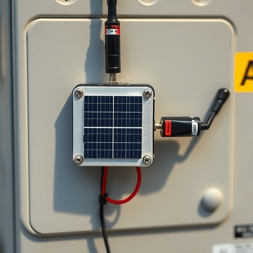
Battery-free IoT sensors are no longer confined to futuristic pilots. As maintenance-free sensing becomes a business-critical feature, engineering teams are looking for a practical way to add them to products that were originally designed around alkaline cells, coin cells, or hardwired power. This battery-free IoT sensors implementation guide focuses specifically on retrofitting existing products — not designing new ones from scratch. The good news is that the transition doesn’t require a full hardware redesign. But it does require a structured approach that accounts for energy availability, communication range, protocol compatibility, and the hidden constraints of legacy enclosures.
Why Retrofitting Is Different from Greenfield Deployment
When you build a new sensor node from the ground up, you can choose components that complement a battery-free energy harvesting design from day one. Retrofitting an existing product is a different exercise. You are working with a fixed physical footprint, a pre-existing microcontroller, and firmware that may never have been designed to handle power interruptions. Before writing a single line of code, the team should inventory the device’s current power architecture:
- Where does power enter the device, and what voltage rails are available?
- Is there a battery holder that can be repurposed as a supercapacitor or storage capacitor bay?
- Can the existing MCU run at very low duty cycles without losing state?
- Is the antenna area accessible enough for a new RF front end?
Answering these questions early will determine whether a product can be retrofitted with minimal changes or whether a small PCB respin is justified. The goal is to extend the product’s life, not to force it into a battery-free architecture that cannot survive real-world conditions.
Step 1: Audit Energy Availability in the Real Environment
Battery-free operation depends on an energy harvesting transducer. But the amount of harvestable energy varies enormously between deployment sites. A sensor in a brightly lit office, for example, may harvest enough photovoltaic energy for a reading every few minutes. The same sensor placed inside a metal junction box will get almost nothing. The first step in any retrofit project is to measure the actual environmental energy at the intended deployment points.
This audit should include more than a single static measurement. Consider daily cycles, seasonal changes, and worst-case conditions such as a windowless storage room or a machine that operates only twice a day. Use a data logger with a low-power energy measurement front end to capture milliwatt-seconds over at least one full week. The resulting profile gives you the minimum energy budget, not the average. That minimum is what your storage capacitor and wake-up interval must be designed around.
Step 2: Select a Backscatter or Harvesting-Ready Protocol
Not all wireless protocols are equally friendly to battery-free operation. Traditional radios such as Wi-Fi and Bluetooth Low Energy consume too much peak current for many energy harvesting sources. For retrofit products, the strongest candidates are passive and semi-passive backscatter technologies, including ambient backscatter and dedicated RFID-based sensors. These protocols leverage a carrier signal from a nearby reader, gateway, or even TV and cellular transmissions to encode data with very little active radio power.
When selecting a protocol, evaluate three factors:
- Range: Can your gateway or reader be placed within the effective range for the product’s operating environment?
- Data rate: Is the byte payload sufficient for temperature, humidity, vibration, or other critical signals?
- Interoperability: Does the chosen backscatter standard integrate with existing industrial IoT platforms, or does it require a proprietary gateway?
Many teams choose a hybrid approach: keep the existing wireless interface for high-bandwidth maintenance tasks, and add a low-power backscatter radio for periodic sensing. This preserves the product’s certification profile while enabling battery-free operation for the primary sensor stream.
Step 3: Manage Power Gating and Cold Start Behavior
In a retrofitted battery-free device, power will not be continuous. The sensor will wake, take a measurement, transmit, and then collapse into a non-powered state. This is a major shift for firmware engineers who are used to always-available voltage. The solution is a careful power management architecture with three key responsibilities:
- Energy storage: A supercapacitor or thin-film battery captures harvested energy until enough is accumulated for one full sense-send cycle.
- Power gating: The storage element is disconnected from the MCU and radio until a voltage comparator indicates the threshold has been reached.
- Cold start logic: The device must be able to boot from a true zero-energy state. That means no reliance on retained RAM or non-volatile variables without a deliberate restore process.
For an existing product, the power-gating circuit is usually the largest hardware addition. It can often be built as a small daughterboard that sits between the energy harvester and the original PCB. This modular approach simplifies certification and minimizes changes to the product’s existing safety-tested layout.
Step 4: Plan for Intermittent Connectivity and Data Semantics
Battery-free sensors do not transmit on a fixed schedule. A reading may arrive every two minutes during a sunny afternoon and then disappear for hours overnight. The cloud platform and data pipeline must treat these gaps as normal behavior, not as failures. This is a semantic change, not just an infrastructure one.
For retrofit projects, consider adding a local cache in the gateway. The gateway can receive a burst of sensor readings and time-stamp them with the arrival time, then forward them upstream in a normalized format. This hides the intermittency from downstream analytics. It also allows you to use a simple publish-subscribe protocol on the sensor side while maintaining a more structured interface for enterprise applications.
Data quality should include an “energy confidence” field. If a temperature reading was taken under low energy conditions, the sensor may have used a lower resolution ADC or a longer settling time. Exposing this metadata allows analytics to distinguish between true environmental changes and artifacts caused by power management.
Step 5: Validate Mechanical and Environmental Compatibility
Retrofitting a battery-free sensor into an existing enclosure is more than a wiring exercise. The new components need physical space, thermal tolerance, and sometimes a transparent window for solar cells or an external antenna port. Before ordering prototype boards, create a 3D model of the existing product and run a quick interference check. Pay attention to:
- Antenna placement: Backscatter performance is extremely sensitive to nearby metal and ground planes.
- Harvester placement: If using photovoltaic cells, the cell needs to be exposed to light. That may require a clear cover or a redesigned label.
- Thermal path: Some energy harvesting ICs generate heat under continuous charging. Confirm that the existing enclosure can dissipate it without affecting temperature-sensitive sensors.
It is also wise to verify IP ratings. Opening a sealed enclosure for retrofitting can compromise ingress protection. If the original product was IP67-rated, the battery-free retrofit should use the same gaskets and potting techniques.
Step 6: Use Existing Gateways and Edge Middleware
One of the common mistakes in a battery-free IoT retrofit is building a new protocol stack from scratch. Most legacy products already have a gateway or edge controller that manages communications. Instead of replacing that infrastructure, integrate the battery-free sensor data into the existing gateway’s abstraction layer. A simple UART or SPI connection between the backscatter receiver and the gateway main board is often sufficient.
On the middleware side, consider a small translation service that converts intermittent backscatter payloads into the same JSON or MQTT topic structure used by the product’s existing sensors. This reduces the burden on cloud dashboards and avoids double maintenance. It also allows operations teams to maintain one visual interface, even though the underlying energy source has completely changed.
Step 7: Create a Certification and Compliance Checklist
Retrofitting an existing product with a new wireless technology means revisiting regulatory compliance. The backscatter radio is likely to operate in a frequency band that was not part of the original certification. That means radio tests, EMC tests, and possibly SAR or exposure assessments need to be repeated. Set up a checklist early in the design phase:
- FCC, CE, or other regional certifications for the new radio technology
- Harmonized standards for low-power backscatter devices
- Battery safety regulations, even if only a supercapacitor is used
- Environmental directives such as RoHS and WEEE for any new PCB
- Antenna gain and spurious emission limits
Do not assume that a module-level certification will cover the whole product. The interaction between the new antenna and the existing enclosure can change radiation patterns. A pre-scan at a certified test lab is far cheaper than a failed application.
Conclusion
Retrofitting existing products with battery-free IoT sensors is an achievable engineering goal if you approach it as a layered integration effort. Start with a realistic energy audit, choose a backscatter protocol that matches your range and payload requirements, and build a firmware architecture that treats power interruptions as normal. The products that succeed will be those that respect the mechanical constraints of the original design while adding a new level of maintenance-free intelligence.